
Rack Reference
How each part of the parallel compressor rack works, what "normal" looks like, and the numbers to keep in your head.
CO₂ Quick Reference
Approximate values for the field — always confirm against a CO₂ P/T chart and the equipment nameplate/manufacturer data.
Approximate — for quick field orientation only. Above the critical point CO₂ is transcritical (no condensation); the HP valve targets the optimum high-side pressure. Always confirm against a CO₂ P/T chart and manufacturer data.
| Temp °F | Press (psia) | Notes |
|---|---|---|
| -51°F | ~120 | Near triple point — caution |
| -40°F | ~145 | Typical LT range |
| -22°F | ~207 | — |
| -4°F | ~286 | — |
| 14°F | ~384 | MT range |
| 32°F | ~506 | — |
| 41°F | ~580 | ≈ receiver pressure |
| Point | Value | Notes |
|---|---|---|
| Triple point | 75 psia | -70°F — below = dry ice |
| Critical point | 1071 psia | 88°F — above = transcritical |
| Flash tank / receiver | ~500-580 psi | Liquid feed pressure |
| Transcritical high side | ~1300-1740 psi | P-optimized for efficiency |
| Gas-cooler approach | 5-9°F over ambient / wet-bulb | With adiabatic pre-cool in heat |
| MT / LT SST | MT ~18-23°F / LT ~ -30°F | Booster suction groups |
| Item | Typical | Notes |
|---|---|---|
| High-side relief | ~1740 psi | System-specific — verify on unit |
| Low/MT-side relief | ~1305 psi | System-specific — verify on unit |
| Standstill MOP | Set below relief | Holds pressure with rack off |
| P-optimization (rule of thumb) | Higher outlet °F → higher target psi | Tune to manufacturer |
| Oil | CO₂-approved POE/PAG only | Moisture forms carbonic acid |
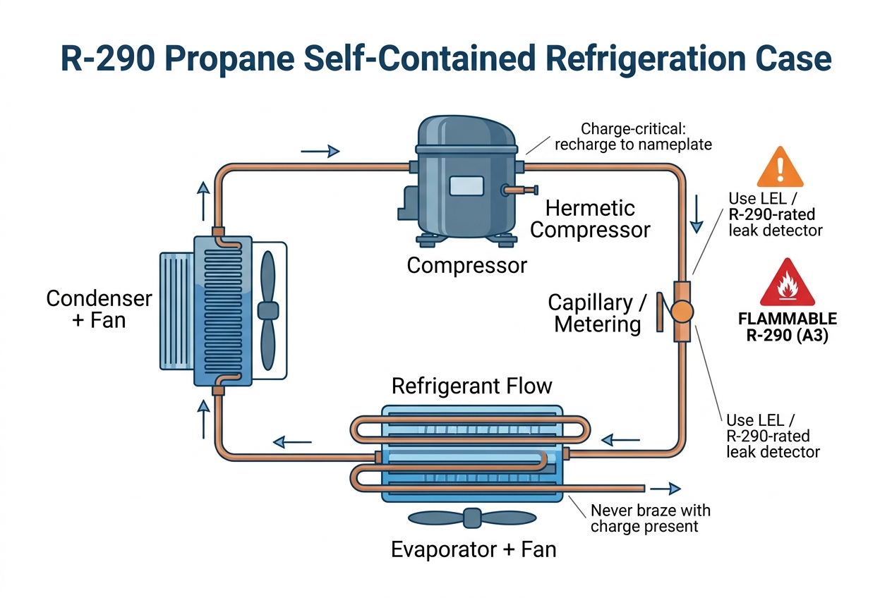
R-290 Field Cheat Sheet
The propane self-contained essentials to keep in your head — always confirm against the case nameplate and manufacturer data.
| Item | Value | Notes |
|---|---|---|
| Refrigerant | R-290 (propane) | A3 — FLAMMABLE |
| Charge size | < ~5 oz / 150 g | Charge-critical — use nameplate |
| Leak detection | LEL / combustible-gas or R-290-rated | NOT a standard halogen detector |
| Power | 120V plug-in (self-contained) | No rack connection |
| Before sealed work | Ventilate + kill ignition sources | No flame/spark/smoking; recover, never braze charged |
| Code | Means | Do |
|---|---|---|
| P1 | Room / thermostat probe fault | Open/shorted room probe — check probe & wiring |
| P2 | Evaporator probe fault | Defrost probe open/shorted — affects defrost termination |
| HA / LA | High / Low temperature alarm | Verify actual temp; check airflow, defrost, load |
| dA | Door open alarm | Door/curtain left open or door switch fault |
| EE / EF | EEPROM / data fault | Parameter memory error — reload parameters |
| cSd | Condenser overheat / probe | Clean condenser, check condenser probe & fan |
Codes vary by exact model/firmware — always confirm against the manufacturer's manual for the specific controller on the case.
Components & Field Examples
Tap a component for how it works, typical values, and an annotated example to match what you see in the field.
A parallel rack stages 2-6+ compressors on a shared suction header to match load efficiently. Capacity is controlled by staging compressors and/or unloaders/VFD lead compressor. Common oil management ties all crankcases to a reservoir.
- Suction group setpoint drives compressor staging.
- Lead compressor may be VFD or have unloaders for fine control.
- Shared oil system: separator, reservoir, filter, and level regulators.
- Each compressor protected by HP, LP, oil-failure, and motor overload.
Discharge 130-300+ psig depending on refrigerant/ambient; suction per group (e.g. low-temp ~ -20°F SST, med-temp ~ +20°F SST).
